Cryogenic High Voltage Lab of KIT-ITEP
The Cryogenic High Voltage Lab was established for supporting high voltage activities of superconducting fusion magnets. Since the 1990s high voltage tasks for cryogenic power engineering were started.
Collaboration with external partners or testing for industry is possible on request.
Table of contents
sprungmarken_marker_673
Main activities:
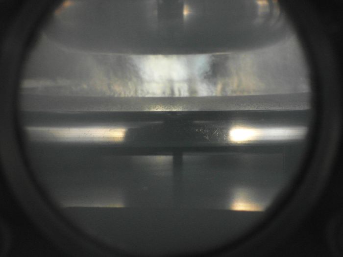
Basic research (e.g. breakdown or flashover voltage of liquid nitrogen for voltages > 200 kV)
Dielectric properties of gaseous, liquid and solid dielectrics were investigated. Present (2020) activities are investigation of flashovers on liquid nitrogen to solid insulator boundaries under DC operation.
Recent publications:
S. Fink and V. Zwecker, " DC breakdown tests with pressurized liquid nitrogen," 2020 IEEE International Conference on Dielectrics (ICD), Valencia, virtual conference, to be published.
S. Fink, V. Zwecker, "15 min DC breakdown tests with liquid nitrogen," 20th International Conference on Dielectric Liquids (ICDL), Roma, Italy, 2019, pp. 1-4.
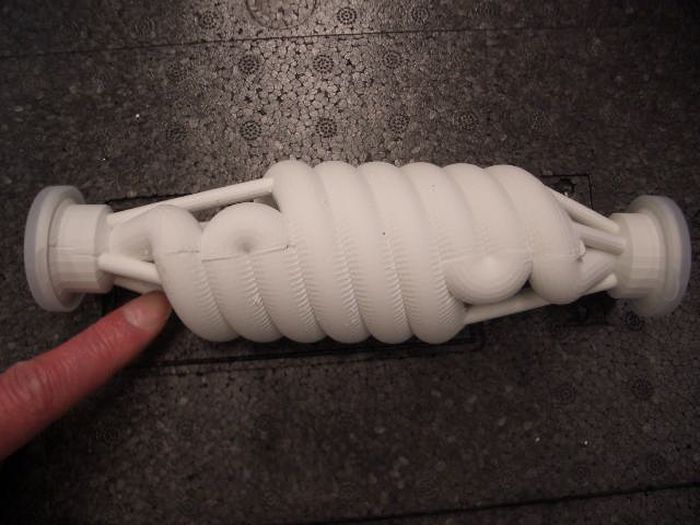
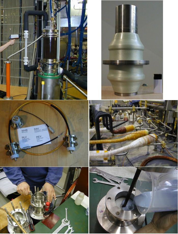
Development of high voltage components (e. g. insulation breaks)
The Cryogenic High Voltage Lab has a long tradition in development and production of a low number of pieces of high voltage components for superconducting fusion magnets (e. g. Euratom LCT coil, Polo Coil, ITER TF Model Coil). Also for ITER developments of prototype were done in collaboration with industry in order to ensure a production process which is compatible for a larger number of pieces.
Cryogenic Components for power engineering were also developed in cooperation with industry (e. g. superconducting fault current limiter).
Publications:
S. Fink, U. Fuhrmann, C. Lange, R. Mueller, V. Zwecker, "3D printed cryogenic high voltage devices," in IEEE Transactions on Applied Superconductivity, vol. 26, no. 3, pp. 1-4, April 2016
W. Fietz, S. Fink, U. Fuhrmann, R. Müller, E. Urbach, V. Zwecker, A. Brummer, R. Oberstarr, C. Wildner, F, Wimmer, K.Woelfl, "Pluggable 56 kV instrumentation feedthrough prototypes for ITER magnets," Trans. on Applied Superconductivity, vol.24, no.3, June 2014
W. Fietz, S. Fink, G. Kraft, H. Scheller, E. Urbach, V. Zwecker, "High voltage testing of ITER prototype axial breaks," Trans. on Applied Superconductivity, vol.23, no.3, pp.4200604-4200604, June 2013
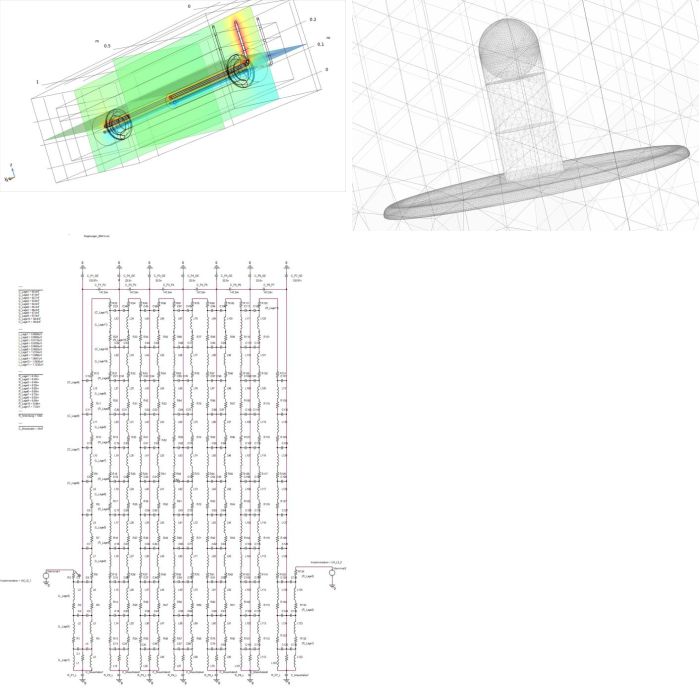
Electrostatic field, FEM and network calculations (e. g. transient electrical behavior of fusion magnets)
Even simple RLC circuits can have (frequency dependent) higher internal voltages than the outer terminal voltage. Frequency depending internal voltage distribution is an important issue for the design of large high voltage apparatus. For superconducting magnets and magnet systems the voltage distribution of the coil system and within different magnets (ITER TF Model coil, ITER CS Model Coil, ITER TF, ITER PF3, ITER PF4) were calculated with network calculation program (PSpice) in frequency and time domain. Coil parameters are calculated analytically or by 2D-FEM.
Electrostatic field calculation can be performed in 2D (BEM and FEM) and 3D (FEM).
Publications:
S. Fink, “Electrostatic field calculations for liquid nitrogen gaps assuming a decisive field factor,” Int. Journal of Applied Power Engineering (IJAPE), Vol.7, No.1, 2018, pp. 65~72
A. Winkler, W. Fietz, S. Fink, M. Noe, "Transient electrical voltages within ITER poloidal field coils," Trans. on Applied Superconductivity, vol.22, no.3, pp.9501304-9501304, June 2012
High voltage support for other facilities, esp. of large size fusion magnets
Mobile equipment makes it possible to perform on site high voltage tests. Especially testing of superconducting large fusion magnets in a special building of KIT-ITEP (TOSKA) was supported.
Publications:
S. Fink, A. Ulbricht, H. Fillunger, A. Bourquard, M. Prevot, "High voltage tests of the ITER toroidal field model coil insulation system," Trans. on Applied Superconductivity, vol.12, no.1, pp.554-557, Mar 2002
S. Fink, S.; W. Fietz, "Long-term high voltage tests of the conductor insulation of a superconducting magnet," Conference on Electrical Insulation and Dielectric Phenomena (CEIDP), pp.357-360, 16-19 Oct. 2005
_4_700.jpg)
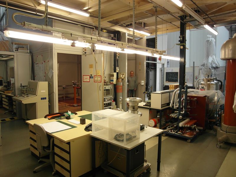
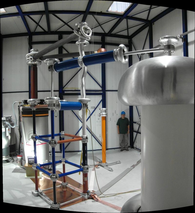
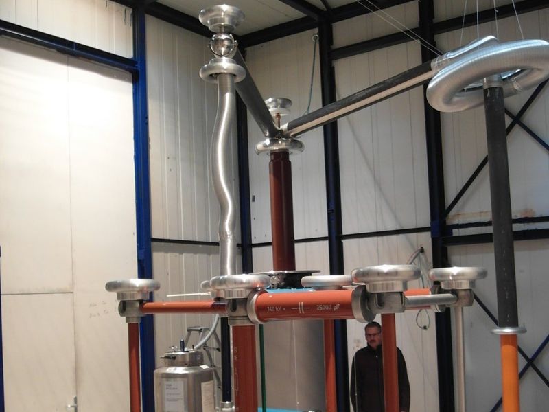
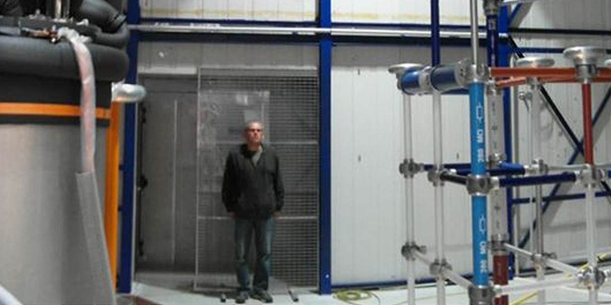
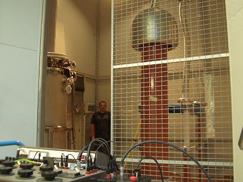
Main equipment:
Main equipment:
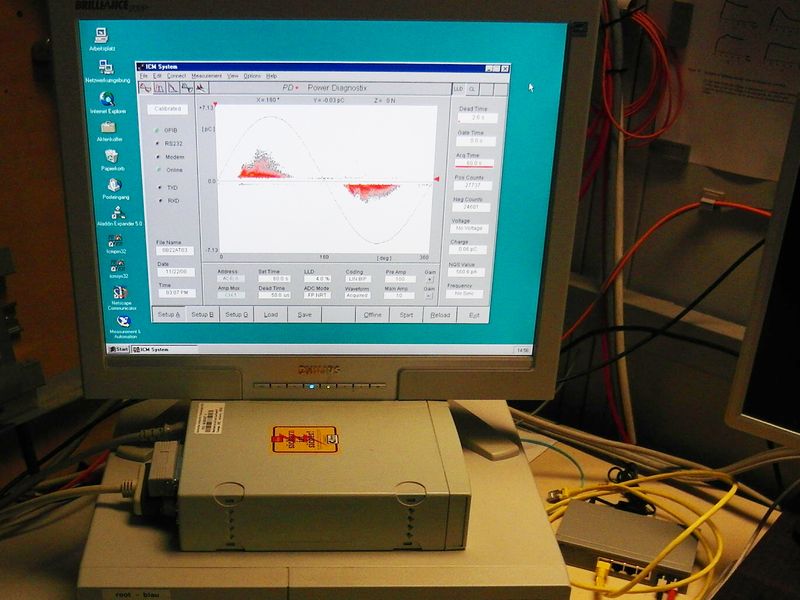
Equipment for high voltage testing with direct, alternating and impulse waveform is available in the Cryogenic High Voltage Lab of KIT-ITEP. Voltage, current, partial discharge, and Schering-bridge measurement can be performed. Several cryostats for liquid helium and liquid nitrogen with diameters up to 650 mm and for different pressures are available. Liquid helium and liquid nitrogen supply is permanently accessible.